Table of Contents
Rotary Encoder in real life
Introduction
In my projects so far, I have implemented Human-Machine Interfaces with buttons, switches, potentiometers etc. or even more elaborate schemes such as browsers and mobile screens. Although I was aware of the Rotary Encoder and the theory of its operation, I have never had the opportunity to build a real project using one of them. Until now.
The first thing in an engineers' mind when solving a problem is to find an existing solution. I have tried several different implementations of algorithms designed for Arduino, which are supposed to read a Rotary Encoder in a manner that is resistant to the contact bouncing problem. Most of the algorithms which provide a reliable solution are based on polling the current state of the switches at regular intervals and implement an elaborate state-machine to deduce status and rotational direction. Other algorithms based on hardware interrupts, employ a small time period to wait during the bounce (debouncing delay) and read again the state when the contacts have calmed down. They can also receive multiple readings at intervals and realize that the state has reached stability when the readings do not change.
Please note that this article refers to a type of rotary encoders known as incremental. The other type is the absolute rotary encoders which operate under a totally different principle. The absolute rotary encoders are far more expensive than the incremental ones and this cost is justified for specific applications only, where it is required to read the actual position of the encoder at any point in time. Consider for example an instrument that shows the direction of the wind. The instrument must report the actual direction of the wind when it starts up and therefore an absolute rotary encoder should be selected in this design. Incremental rotary encoders are less expensive but even they may require additional resources to operate properly in a particular application. Consider a simple case of a volume control button. One would expect that when the apparatus is turned on, the volume would be set at the position it had when it was turned off. Meaning that the current volume setting should be stored in a non-volatile memory. Only if we decided that the volume would be set at a specific (e.g. 1 of 10) setting any time the apparatus would be turned on, then the memory would not be required.
Back to the incremental encoders then. In my project, due to the limited available resources and the nature of the system, it was not acceptable for the software neither to waste time waiting for anything, nor to add additional hardware, such as a monostable nor to use a more expensive encoder such as a debounced optical encoder. I wanted a purely software, interrupt-based solution that would deduce the state of the rotary encoder directly upon invocation. After lots of searching and trying, I came across the article "Bounce-Free Rotary Encoder" by David Johnson-Davies of http://www.technoblogy.com, which presented what I consider as the most elegant and reliable solution on-line.
I have spent some time getting acquainted with David's solution and I have identified a few intricacies that are inherent to the design, that I considered worthwhile to document. In addition, the diagrams that I have created may be useful to those who want to dive into the internals of the Rotary Encoders.
One of the reasons for writing this article is because I find it extremely remarkable how such a mundane thing, like “reading two input pins” requires so much effort and knowledge to deal with; and still is not solved 100%. At times when sensors are full-blown computers and interfacing with them is performed by just dropping a library into the code and typing a few commands, reading two contacts still bring us back to the basics, requiring expertise in electricity, electronics and algorithms! Perhaps, junior engineers can bring the case as an example to their managers, when such managers demand them to built a Mars Rover “by tomorrow” 
If you are familiar with how Rotary Encoders work and you are are only interested in the debouncing method, you can go directly to Explanation of the de-bouncing method.
Theory of operation
Rotary Encoders are based on the principle of utilizing several signals that are encoded in a binary form, so that any transition causes the change of just one single bit. For an explanation of the basics, you can consult the following Wikipedia articles:
In this article, we will explore a simple form of Rotary Encoder which provides as outputs two signals, A and B. Most encoders labeled as EC11 or KY-040, are based on this principle. Please note that not all rotary encoders behave exactly the same, especially during transition from one state to another, depending on their construction. I will try to implement a universal solution, applicable to most rotary encoders variants. It is understood that this approach may have implications which may or may not affect a specific implementation and should be considered thoroughly at the design phase of each project.
In theory, we learn that signals A and B “are in quadrature” or “are 90 degrees out of phase”.
We also learn that “if A leads B, the shaft is rotating clockwise” and “if A lags B, the shaft is rotating counter-clockwise”.
In the following, we will see how these things work in a more analytical presentation.
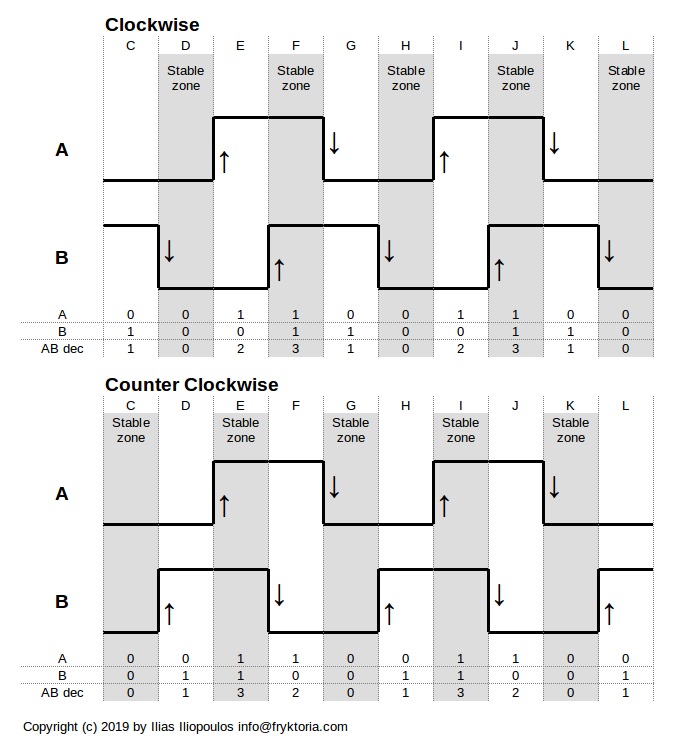
A diagram presenting both signals, as the shaft of the encoder rotates in the clockwise and the anti-clockwise direction, is shown below (Diagram 1). In the diagram, the time instances are shown as columns, named C, D, E, … etc., progressing to the right side of the diagram.
The transition of the signals are shown with arrows, so that the reader can focus on what is happening at the transition point, which is the point of interest in an interrupts-base solution. The arrows are placed purposely on the right side of the transition, in order to correspond with the new binary state of the signal which is shown on the table below the diagram.
Starting with time instance in column C, in the upper part of the figure (Clockwise) we see that A is LOW and B is HIGH. Accepting a notation of LOW = 0 and HIGH = 1, we have A = 0, B = 1 and consequently AB = 00 (binary) which is same as AB = 0 (decimal). In the following, I will refer to AB only in its decimal form, because it is easier, at least for us humans, to identify the state transition sequences.
Going back to Diagram 1, at the end of time instance C, signal B goes LOW, while signal A remains LOW. Most rotary encoders designed to be operated by humans (in contrast to other encoders which are moved and controlled by machines), employ a mechanism to temporarily “lock” the shaft in this resting position, which is the “detent”. Turning the shaft right or left of this position, you feel a distinctive “click” when you move to the next stable position. These positions are shown as “stable zones” in the diagram. Therefore, in the types of encoders that we examine, we will consider the change from one detent to the immediately neighbouring detent, either on the right side or the left side, as one identified change in our position indication.
NOTE: The stable zones had been a source of controversy since I have received several emails regarding implementations of other encoder manufacturers where the signal transition from one step to another and the detents did not follow the above principle. For example, one detent might correspond to a change of a single signal, either A or B, according to the Gray encoding. The reason that I have not covered this case in this section relates:
a) to the fact that the common EC11, KY-040 variants produce two Gray code transitions per detent. As per the KY-040 datasheet:
A rotary encoder has a fixed number of positions. These positions are easily felt as small clicks when you turn the encoder. The KY-040 module has thirty of these positions……. In each encoder position, both switches are either opened or closed. Each click causes these switches to change states as follows: * If both switches are closed, turning the encoder either clockwise or counterclockwise, one position will cause both switches to open. * If both switches are open, turning the encoder either clockwise or counterclockwise, one position will cause both switches to close.
b) to the principle of the debouncing algorithm 2. A transition is considered valid when both signals (A and B) change value presented below. Therefore, I considered that even in the case where one detent corresponds to a change in only one signal, the user should make two shaft movements, or in the generic case, as many movements as necessary so that both signals are changed. This obviously has the effect that the Gray code will move two positions instead of one. This is a side-effect of this debouncing algorithm and the price to pay if we do not debounce with hardware.
If we consider signal A the most significant bit (MSB) and B the least significant bit (LSB) of a binary number composed of A and B, we can see that when the shaft is not rotating, it rests at state 00 (which is decimal 0), or at state binary 11 (which is decimal 3).
In the clockwise direction, moving from stable state 0 (column D) to stable state 3 (column F), the encoder needs to pass through state 2 (column E). Then, to go from stable state 3 (column G) to stable state 0 (column H), the encoder needs to pass through transit state 1 (column G). So, we have a pattern 0-2-3 and 3-1-0 to go from one stable state to the next, rotating clockwise.
In the counter-clockwise direction, moving from stable state 0 (column C) to stable state 3 (column E), the encoder needs to pass through transit state 1 (column D). Then, to go from stable state 3 (column E) to stable state 0 (column G), the encoder needs to pass through transit state 2 (column F). So, we have a pattern 0-1-3 and 3-2-0 to go from one stable state to the next, rotating counter-clockwise.
After we have seen how the states of the signals change through time, we understand that we can deduce the direction of rotation by identifying the pattern of the sensor readings. If our sensors read the pattern 0-2-3 or 3-1-0, the shaft is turning clockwise. If we read the pattern 0-1-3 or 3-2-0, the shaft is rotating counter-clockwise. This is the magic of the Gray encoding.
Looking at the transition points
As a result of the Gray encoding, only one of the signals changes at a time. As we see in Diagram 1, in the transition between column C and D, signal B changes state while signal A remains stable. At the next transition between columns D and E, signal A changes state while signal B remains stable. This is a very useful observation that will be extremely helpful below.
The bouncing problem
The problem with electro-mechanical switches is that when a contact between the two wires makes or breaks, the two wires jump momentarily, creating a series of unwanted pulses. This is an over-simplification, because there are also additional issues which cause the bouncing effect. In addition, the input pin may have a range where the voltage level is not identified clearly as logic HIGH or LOW. Stray capacitance or even capacitance from RC filters inserted to fight bounce in some designs(!) may keep the voltage at this range for quite some time. If the input of the MCU does not provide some form of hysteresis, such as a Schmitt Trigger, the results can be unpredictable. Finally, strong electromagnetic interference (EMI) can be a source for unwanted pulses. Arm yourself with some patience, if you want to dig into the matter and read this article by Jack G. Ganssle.
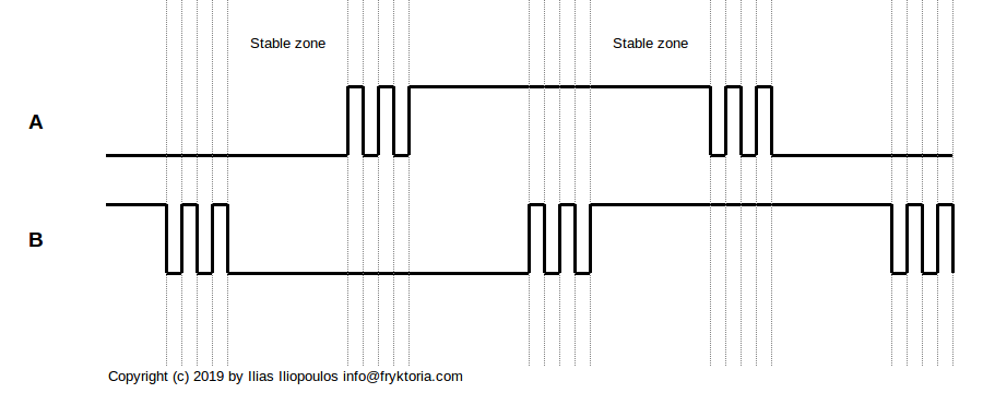
The bouncing phenomenon is shown graphically in the diagram below. When a signal changes from one state to the other, several pulses may be produced before the signal rests to its final state. Some of them may produce the value AB = 0 or AB = 3 and be mistakenly identified as stable zone in the detent.
Most algorithms try to eliminate the bouncing problem by examining whether the rotation creates strictly the known patterns (0-2-3, 3-1-0, 0-1-3, 3-2-0). Anything different will be considered illegal and will not be identified as a known rotation. The problem with this method, is that although we have moved the shaft of the encoder, in the case of illegal patterns the system does not respond. If for example we use a knob to change the value at a display, sometimes we may need one “click” to change the value from e.g. number 7 to 8, and other times two or three clicks. This behaviour is certainly not acceptable. We definitely want each and every click of the encoder to produce one response from the system.
Yet, bouncing is a fact of life (and not only of electro-mechanical contacts 
Explanation of the de-bouncing method
The debouncing method presented by David Johnson-Davies makes use of the following principles:
1. When one signal changes state, the other is stable
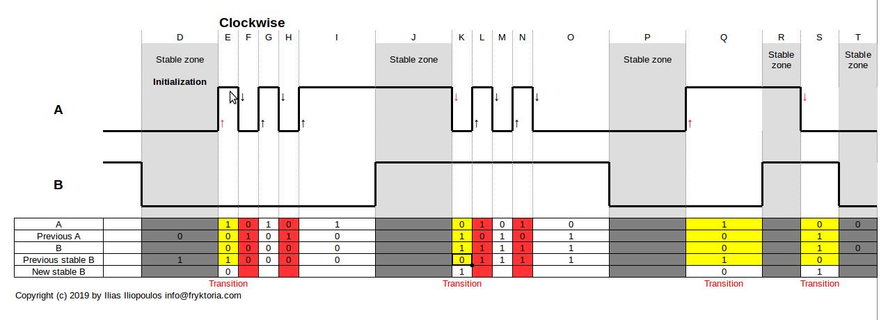
This is a result of the phase shift between the two signals. We assume that bouncing of one signal has ended before the other signal changes state. This sets a limit to the maximum speed of rotation of the shaft. Considering that bouncing takes place for 20 milliseconds and as shown in Diagram 2, at the end of the bouncing (column I) the state of signal A is at its stable and resting point, the maximum rotation speed (if column I is of almost zero duration) is 1/20ms = 50 transitions per second. I have experienced switches with longer bouncing issues, such as 100ms, so I would consider safe a maximum rotational speed of 10 transitions per second. This value can be within the limits of a person trying to abuse the shaft, but remember that we need to design considering that this type of abuse is part of the ordinary life of an electronic equipment.
2. A transition is considered valid when both signals (A and B) change value
This is a result of the detents, having stable zones when the signals AB are in state 0 or 3. So, whatever happens at the state of each switch during the progress of time, such as bouncing, is irrelevant if the outcome is not causing a change in both signals. This principle has consequences when the direction of the rotation changes, as we shall examine below.
Taking the above principles under consideration, we must first identify that a valid transition has taken place.
Diagram 2 presents in detail the state of the signals, as well as the state of the variables in the debouncing algorithm. Please note that each transition of signal A causes an interrupt. The interrupt service code must be fast enough to finish its work before the next interrupt.
It is also worth mentioning that the rotational movement is identified at the beginning of the bounce, as indicated by the red arrow. This makes the algorithm more responsive, in contrast to other algorithms based on a debouncing delay. Such algorithms should wait until the end of the bounce to identify a steady state and subsequently infer the transition.
The next step will be to identify the direction that the shaft has moved. Because the code may work with interrupts, we have to explain how they affect the design.
Using hardware interrupts
One major design consideration, especially in low resource systems, is that one microcontroller (MCU) needs to perform several tasks. If an event occurs while the MCU is busy handling another task, the event may be lost.
Although the debouncing method described above can be implemented with regular sampling of the state of the signals, a more efficient method can use hardware interrupts to signal the rotation of the shaft. The interrupt could also be used to wake-up an MCU that has been put into low power consumption hibernating mode.
We could use both signals A and B to create two distinct interrupts, by connecting each one of the encoder pins to an interrupt enabled MCU pin. Although ATMega328 and other MCUs can configure several I/O pins to respond to interrupts, the Arduino IDE core allows only two interrupts at digital pins 2 and 3. To save an interrupt for the MCU to be used for another purpose, we are using only one single interrupt pin. We connect this pin to the encoder signal A. Therefore, the code that reads the encoder should rely on a change in pin A to make its magic.
Interrupts on Arduino pins 2 and 3 can be configured to detect either the rising edge of a pulse or the falling edge of the pulse or even the logic state. The interrupt handling functionality of other I/O pins is limited to detect a logic “change”. It is our responsibility to detect if this change was caused by a rising or a falling edge. To do that, we must read the signal value immediately after the interrupt. For a flexible code that can be extended to cope with additional pins, the code uses interrupts set to CHANGE (see this Arduino reference page).
Finally, we have made the assumption that reading the state of the pin immediately after the interrupt, we shall have the signal value that caused the interrupt. The MCU is very fast and this is not a problem for simple systems, but the assumption may not be always true. If, for example, after our interrupt routine starts working, another interrupt from another source takes over and when it returns to service out task, the value of signal A has changed, this will cause an undesirable situation. Another example is when several I/O pins share the same interrupt handling code. This issue must be taken into consideration and the priority of handling the interrupts must be carefully designed in a properly functioning system. It must also be tested extensively because interrupts are asynchronous events and the problems, if any, wait for a particular combination of events in order to manifest themselves in all their glory!
Identification of direction
After coping with the problem of identifying a valid rotation, free from bouncing pseudo events, we then must understand if the encoder's shaft has rotated right or left (or up/down or clockwise/counter-clockwise).
Referring to Diagram 1:
- If signal A goes 1 and finds B at 1, A lags B and rotation is counter-clockwise (columns E and I, bottom part).
- If signal A goes 1 and finds B at 0, A leads B and rotation is clockwise (columns E and I, top part).
- If signal A goes 0 and finds B at 1, A leads B and rotation is clockwise (columns G and K, top part).
- If signal A goes 0 and finds B at 0, A lags B and rotation is counter-clockwise (columns G and K, bottom part).
The above “truth table” tells us that when A equals B, the rotation is counter-clockwise and when A is different than B, the rotation is clockwise.
One can easily get puzzled by this; “but we know that the steady state is when A and B are either both 0 or both 1. Why not A=B?”. The answer, as you can see on Diagram 1, is that the code runs when A changes and therefore the value of B at that time is the inverse of B's steady state.
So,
      if (a) {
        // Rising edge of A, new a=1
        if (b)
          changeRotaryValue(false); // a=1 and b=1, CCW
        else
          changeRotaryValue(true);  // a=1 and b=0, CW
      } else {
        // Falling edge of A, new a is 0
        if (b)
          changeRotaryValue(true);  // a=0 and b=1, CW
        else
          changeRotaryValue(false); // a=0 and b=0, CCW
      }
or more simply:
      if (a == b) {
          changeRotaryValue(false); // CCW
      } else {
          changeRotaryValue(true);  // CW
      }
or even simpler:
changeRotaryValue(!(a == b));
First-click problem and Change-of-direction problem
If you implement the code in the "Bounce-Free Rotary Encoder" by David Johnson-Davies, you will notice two peculiarities:
- the first click after start, 'may' or 'may not' change the count value. You will notice that this depends on the current state (0 or 3) of the encoder upon initialization.
- Although when rotating at the same direction, the count value changes by one after each click, when the direction of rotation changes, the first click after the rotational change is lost.
Both issues result from the debouncing principle “A transition is considered valid when both signals (A and B) change value”, in combination with the fact that the identification of a transition takes place only when signal A changes.
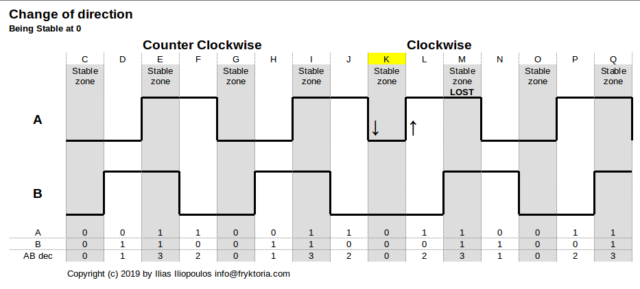
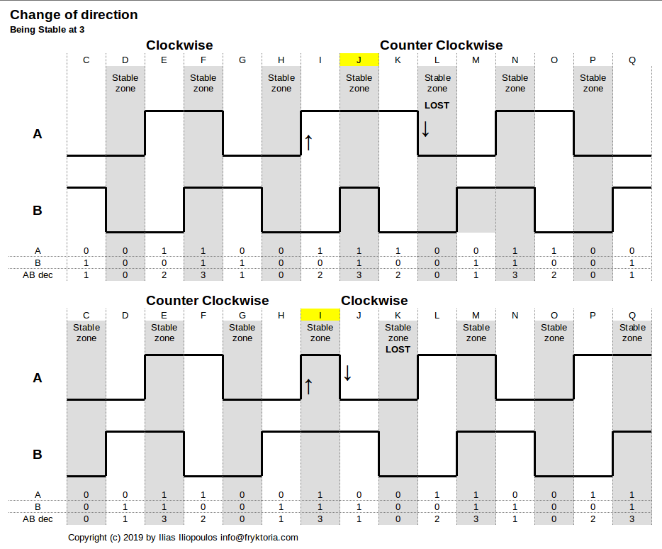
Diagrams 3 and 4 present what exactly is happening.
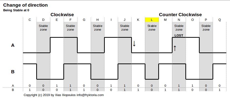
Diagrams 3a, 3b show the events when the rotation direction changes after the encoder has rested at state AB = 0, and Diagram 4 at state AB = 3. The bouncing of the states is not shown in the diagrams because we deal only with the stable, debounced state which is the result of the algorithm.
In Diagram 3a, we notice that the shaft has been initially turning clockwise. When the switch is at state 0 in time instance of column L, the next rotation takes place at the opposite direction. The new interrupt that identifies this change of detent is happening between columns M and N and the state of B after the transition is 1. The previous interrupt that has led the encoder to column L has taken place between columns J and K and the value of B was again 1. Therefore, A changes but B does not, and the click is not identified as a valid rotation.
We also see here that if we had employed two interrupt pins, one for signal A and another for signal B, the state of B which has changed between column K and L, might have been recorded. But this is not within the scope of this documentation. The mandate is to use one single interrupt pin.
In Diagram 3b, we notice that the shaft has been initially turning counter-clockwise and has rested at column K. The interrupt caused by the falling edge of signal A found B = 0. Change of direction to clockwise while B is 0 means that A will rise first, which happens between columns K and L. But the interrupt caused by the rising edge of A between columns K and L finds B = 0, which is equal to the previous value. So, the click is not identified as a valid rotation.
The signal patterns are different when the change of rotation takes place when the encoder rests at state AB = 3, as shown in Diagram 4. The explanation though is similar. Identify the two states of B at the time of the interrupt caused by the change of signal A immediately before and after the rotational change. You shall see that B retains its value, and therefore our counter will miss a step.
Summary
A brilliant debouncing algorithm for Rotary Encoders is published by David Johnson-Davies. The benefits are:
- Simple and elegant code
- Supports interrupts
- Works on both the rising and falling edge of pulses, allowing the use of any MCU I/O pin supporting interrupts
- Requires one single interrupt of the MCU for the rotary operation
- Is not based on debouncing delay. Does not rely on time at all!
- Responds instantly to user action
- Achieves the maximum possible speed of rotation.
Minor operational flaws are identified, which are inherent in the design. Upon initialization, the first click on one direction is lost. Also, one click is lost upon change of rotational direction.
These flaws are minor, when dealing with rotary encoders operated by humans, but may be significant when the algorithm is intended to be used in automated environments.
Can we fix those flaws? Regarding the missed step at the change of rotational detection, the answer is no, because B must have changed from its previous value at the time when A changes value. This is inherent to the debouncing algorithm and we will have to live with it.
What about the random change at the first click after the program starts? Of course, we cannot control the resting state of the encoder. But what we can do, is enhance the code by reading the current state of B when the program starts and set the value of the previous B, depending on the current state of the switch and the intended or the expected direction of the first rotation.
For example, consider that our implementation has a counter displaying only positive values (e.g. from 1 to 10) and the value is increased with a clockwise rotation. We can setup the system so that the first “lost” detent will occur at the same clockwise rotation. Starting from the initial point of counter = 1, the first right click will be lost and the second right click will set counter = 2. If the user changes direction and turns left, the first left click will be lost, but the second left click will return the shaft to the starting position of 1.
Another workaround to make the operation of the encoder to be consistent in each and every step, instead of “fixing” the problem, we can “expand” the problem to all transitions. If for example, after each transition, we set the previous state to a wrong value, the encoder will not recognize the direction of the next step. This way, each position change will require two clicks, regardless of the direction. This feature is implemented in the library.
Finally, it seems that to deal completely with the bouncing problem, a hardware solution (monostable multivibrator, flip-flop, RC filter followed by Schmitt trigger etc.) is the proper thing to do. If no such resource is available, or such a level of accuracy is not mandatory, such as for hobby projects, the next best thing is the algorithm described above.
Note: During my tests with an Arduino Uno or Nano, I have noticed that the pins of PortD (PD0 - PD7) seem to have a much better tolerance to bouncing than PortB. But this is just a feeling and perhaps the subject of another research.
The library
The debouncing method principle has been used to implement an Arduino library. The rationale was mostly to document several issues that I have learned during my research on the subject.
In addition to the rotary encoder, the code has provision for a push-button which is integrated in the shaft of the rotary encoder. Being an electro-mechanical switch, this push-button also suffers from bouncing problems, that are coped with by the standard debouncing delay method.
Please check the Github page for a description of the functionality available and to download the library. Several examples which demonstrate the library features are included.

